
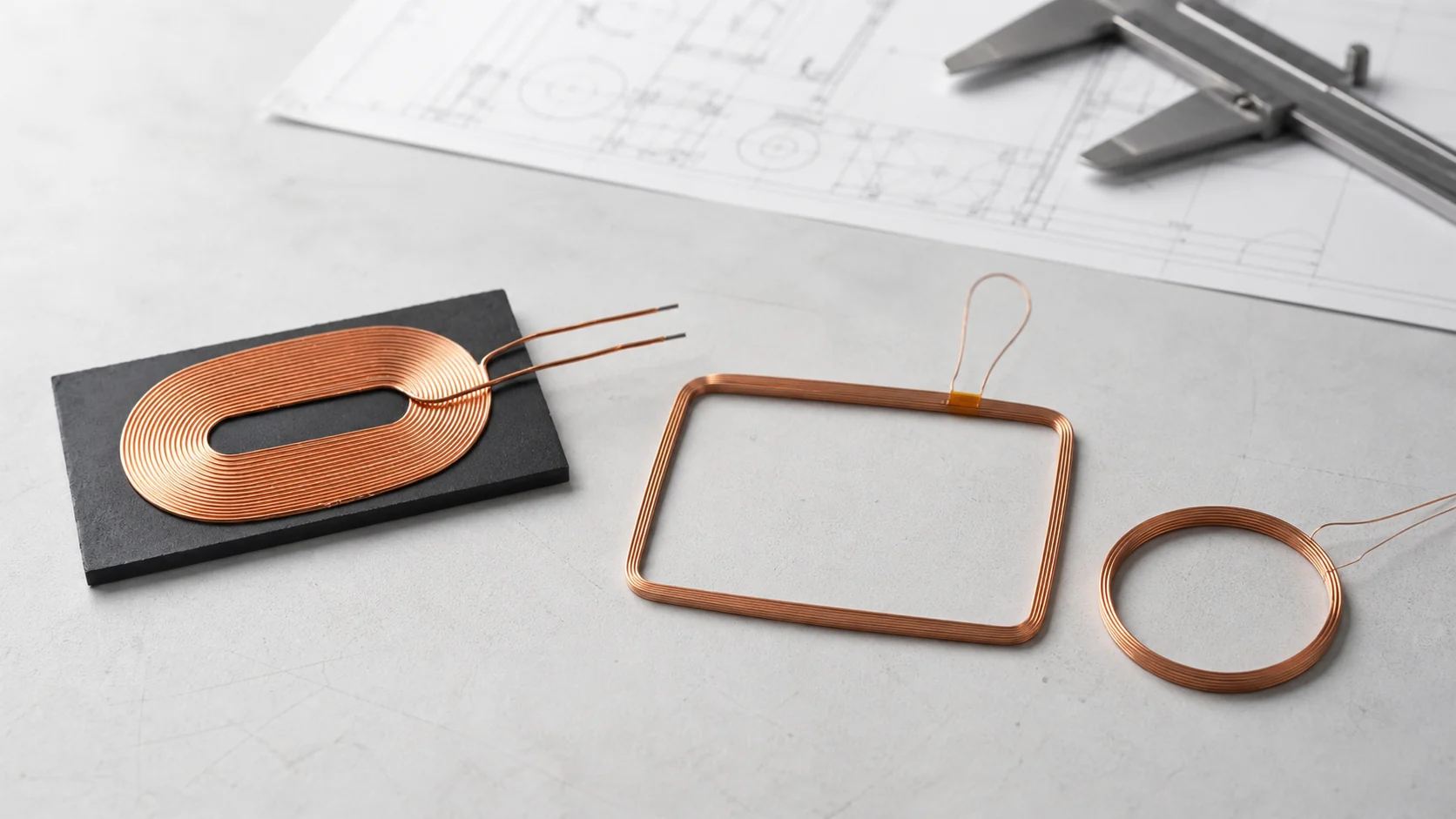
A coil can look simple on a schematic and still become one of the hardest components to industrialize. Its electrical behavior depends on its physical construction, while its physical construction must fit your enclosure, assembly process, thermal limits, and production tolerances.
That is why sourcing a custom electronic coil OEM is not the same as buying a catalog inductor. The best results come from treating the supplier as an engineering and manufacturing partner from the beginning?not as a vendor that receives a drawing only after every decision has already been made.
This guide explains what product engineers should prepare, how development normally progresses, how to validate samples, and what to examine before approving a coil winding manufacturer for volume production.
The short version: what your RFQ should include
If you need to contact a manufacturer quickly, send these items first:
- application and coil type;
- target inductance, tolerance, and measurement frequency;
- maximum DC resistance (DCR);
- operating frequency or frequency range;
- mechanical envelope, including maximum height;
- current, voltage, power, and temperature conditions where relevant;
- wire, core, shielding, or structural preferences, if already known;
- lead termination and assembly requirements;
- expected sample quantity, annual volume, and ramp timing;
- drawings, photos, CAD files, or an existing sample.
The most commonly missed item is the measurement condition. An inductance target without test frequency, fixture, and tolerance can create disagreement even when both sides are measuring the same part correctly.
Why custom coils are different from catalog components
Resistance and capacitance are often selected from standardized values and packages. A custom coil is different because geometry is part of the electrical design. Wire diameter, turn count, winding pitch, layer arrangement, core or ferrite material, lead routing, and final forming dimensions all affect performance.
The surrounding product also matters. A nearby battery, PCB ground plane, metal enclosure, ferrite sheet, magnet, or mounting adhesive can change inductance, coupling, losses, temperature rise, or resonant behavior. A coil that meets its target on an LCR meter in free air may perform differently after it is assembled into the product.
For wireless power, RFID/NFC, compact sensors, and high-frequency air-core inductors, the physical and electrical design must therefore be developed together. A standard coil can still be the right choice during proof of concept, but custom development often becomes necessary when the final product has fixed space, efficiency, tuning, or assembly constraints.
Three common custom coil types?and what matters most
Wireless charging coils (TX and RX)

Transmitter and receiver coils for wireless power transfer are highly sensitive to geometry and system integration. The design must fit a limited footprint, achieve the required coupling and efficiency, control temperature rise, and operate with the selected power architecture. If the product must meet a particular wireless charging standard or certification program, that requirement should be stated at the start.
Key engineering priorities include:
- Winding geometry. Outer dimensions, inner opening, turn spacing, layer count, and coil-to-coil alignment influence coupling and usable installation tolerance.
- Current capacity and temperature rise. Wire construction and DCR must support the intended power level within the product’s thermal environment.
- Ferrite and shielding. Ferrite geometry and material can affect effective inductance, losses, field direction, and nearby electronics.
- System-level validation. Measure efficiency and temperature in the real assembly across the expected alignment, gap, input, and load range?not only at the nominal point.
Sensync’s wireless charging coil and custom electronic coil capabilities cover development from customer drawings, samples, or application requirements.
RFID and NFC antenna coils

RFID and NFC coils operate as near-field antennas. Their inductance works with the tuning network and the parasitic capacitance of the complete assembly, so the relevant target is usually not inductance alone but the behavior of the tuned system.
Key engineering priorities include:
- Inductance and tolerance at a defined test frequency. Measurement conditions must match the design intent.
- Resonance and Q factor. These should be evaluated with the intended chip, capacitor network, PCB, enclosure, and nearby materials.
- Form factor. Flat cards, small readers, wearables, cylindrical tags, and embedded modules require different winding and lead structures.
- Mechanical stability. Self-bonding wire can create a compact, self-supporting coil without a bobbin, but the bonding process and handling method must be controlled.
For 125 kHz, 134.2 kHz, 13.56 MHz, or another operating frequency, state the complete system standard and test configuration rather than assuming the frequency alone defines the coil.
Air-core inductor coils

Air-core coils use no magnetic core. They can be useful where core saturation, magnetic material losses, weight, or very-high-frequency behavior makes a magnetic core undesirable. Their geometry is especially important because there is no core to establish or stabilize the magnetic path.
Key engineering priorities include:
- Dimensional repeatability. Diameter, length, pitch, and turn count directly influence inductance and parasitic behavior.
- Self-supporting construction. Self-bonding wire, sleeves, fixtures, or potting may be used to maintain shape through handling and assembly.
- DCR and current capability. Wire size and total conductor length must balance losses against the available space.
- Lead geometry. Lead length, orientation, forming, stripping, and tinning can affect both assembly and high-frequency performance.
What to prepare before contacting a coil manufacturer
A complete production drawing is helpful, but it is not always required for the first engineering review. A manufacturer can often help close design gaps if the application and constraints are clearly described.
Electrical requirements
Provide the target inductance and tolerance together with the test frequency and, where important, test voltage, fixture, bias, or temperature. Also include maximum DCR, Q-factor requirements, self-resonant frequency, rated current, saturation concerns, insulation requirements, and any system-level efficiency or read-range target.
Do not turn every desired value into a tight component tolerance without discussing tradeoffs. Overly narrow tolerances can reduce yield and increase cost without improving the finished product. Identify which parameters are critical to function and which are preferences.
Mechanical requirements
Supply a dimensioned drawing or at least a space envelope with maximum length, width, and height. Include keep-out zones, inner openings, lead exit direction, lead length, stripped length, tinning, connector requirements, adhesive or ferrite placement, and any flatness or forming requirement.
If you have a 3D model, assembly drawing, fixture, or physical sample, share it early. A coil can meet its own drawing and still conflict with a boss, screw, battery edge, housing rib, or pick-and-place process in the final product.
Operating and compliance environment
Describe operating and storage temperatures, duty cycle, vibration, humidity, chemicals, sterilization, potting, and the regulatory or industry environment. Automotive, medical, aerospace, and safety-critical applications may require additional qualification, change control, documentation, or traceability.
Commercial and program information
State prototype quantity, pilot quantity, expected annual usage, target production start, destination market, and any packaging or labeling requirements. Volume affects the recommended process, fixture investment, automation level, inspection plan, and unit-cost model.
The OEM coil development process
Custom coil development usually follows five stages. The exact timing depends on complexity, material availability, tooling, qualification requirements, and the speed of technical feedback.
| Stage | Supplier output | Customer decision or input |
|---|---|---|
| 1. Feasibility review | Proposed structure, open questions, preliminary process and quotation basis | Confirm priorities, constraints, test conditions, and target volume |
| 2. Prototype build | Initial samples, dimensional data, and electrical measurements | Test in the actual assembly and report results under controlled conditions |
| 3. Design iteration | Revised winding, materials, forming, or lead configuration | Confirm whether changes solve system-level issues |
| 4. Golden sample approval | Locked drawing, BOM, process settings, inspection criteria, and approved sample | Sign off the golden sample and production acceptance limits |
| 5. Pilot and volume production | Controlled production, inspection records, packaging, and traceability | Review pilot capability and approve ramp to regular supply |
Stage 1: engineering and feasibility review
The manufacturer checks whether the target can be produced consistently with the available wire, tooling, winding process, and inspection methods. A useful review does more than say ?yes? or ?no.? It identifies conflicts?for example, a DCR limit that cannot be met within the stated space?and proposes specific tradeoffs.
A straightforward review may take only a few business days, but unusual materials, tight packaging, or incomplete requirements can extend the discussion. A fast answer is less valuable than an answer that exposes risks before samples are built.
Stage 2: prototype development
The supplier produces a small sample lot using the proposed design. For a typical project, this may be a handful to a few dozen pieces, depending on the tests you need to run. Request actual measured data rather than only a pass/fail statement.
At minimum, the sample report should identify the test instrument or method, measurement frequency, environmental condition if relevant, sample size, and individual or summarized results for the critical parameters.
Stage 3: integration testing and design iteration
Test the samples in the real product or a representative fixture. For wireless charging, check alignment, gap, load range, temperature, ferrite, and nearby metal. For RFID/NFC, test the complete tuning network, tag or reader IC, enclosure, mounting material, and realistic target objects. For air-core inductors, verify the operating frequency, waveform, current, temperature rise, and mechanical stability.
When reporting a problem, send measured evidence and the exact test setup. ?Inductance is low? is less actionable than ?8.7 ?H measured at 100 kHz and 1 V in the assembled module; target is 10.0 ?H ?5% under the same condition.?
Stage 4: golden sample and production release
After the design passes validation, approve a golden sample and freeze the production definition. The release package should cover:
- drawing revision and bill of materials;
- wire manufacturer or approved equivalent, conductor size, and insulation system;
- turn count, winding direction, pitch, layers, and forming dimensions;
- ferrite, adhesive, tape, sleeve, connector, or other secondary materials;
- lead preparation and termination;
- electrical and dimensional test methods;
- acceptance criteria, sampling plan, packaging, labeling, and traceability;
- rules for material, equipment, process, or sub-supplier changes.
This production record is what allows future orders to reproduce the approved result.
Stage 5: pilot run and mass production
Use the pilot run to verify that the process works beyond a few engineering samples. Review yield, process capability on critical characteristics, inspection data, cycle time, handling damage, packaging performance, and any difference between prototype and production equipment.
For repeat orders, agree on batch identification, record retention, non-conformance handling, corrective-action expectations, and notification before controlled changes.
How to evaluate a custom coil manufacturer

Price and sample appearance are not enough. Evaluate whether the supplier can control the variables that determine performance at your required scale.
| Evaluation area | What to ask for | Warning signs |
|---|---|---|
| Engineering response | Technical questions, assumptions, tolerance tradeoffs, and a manufacturable proposal | Quote provided without clarifying missing test conditions or application constraints |
| Winding process | Equipment type, tension control, tooling, parameter control, and capability for your wire/geometry | Heavy dependence on operator judgement with no defined process window |
| Measurement capability | Instruments, calibration, fixtures, test frequency, gauge R&R where appropriate | Measurements reported without conditions or traceable method |
| Prototype-to-production transfer | Whether samples and production use equivalent materials, settings, fixtures, and inspection logic | Prototype process cannot be reproduced on volume equipment |
| Quality system | Incoming, in-process, and final inspection; non-conformance and corrective action; certification relevant to your program | Certificate shown, but no evidence of batch-level control |
| Traceability and change control | Lot traceability for wire and critical materials; drawing revision; notification rules | Materials or processes may change without customer approval |
| Capacity and continuity | Capacity at target volume, maintenance, backup equipment, material lead times, and surge plan | No credible plan for repeat orders or equipment downtime |
Look for process capability, not a headline precision number
A machine’s nominal positioning resolution does not prove that the finished coil will hold every electrical and mechanical tolerance. Ask for capability data on the characteristics that matter to your product: inductance, DCR, dimensions, flatness, lead position, or another critical-to-quality feature.
For established or higher-volume projects, request a pilot run with enough pieces to evaluate distribution and stability. Depending on program risk, that may include control charts, Cp/Cpk or Pp/Ppk, gauge studies, first-article inspection, PPAP-style documentation, or an agreed equivalent.
Verify what is actually done in-house
Ask which operations are performed at the quoted facility: winding, forming, bonding, ferrite or adhesive assembly, soldering, electrical testing, dimensional inspection, and fixture fabrication. Outsourcing is not automatically unacceptable, but every external handoff must have defined control, traceability, and lead-time ownership.
Evaluate communication during the sample stage
The prototype phase is a useful preview of the production relationship. Strong suppliers document assumptions, respond with measured evidence, track revisions, and explain tradeoffs. Slow, vague, or purely sales-driven communication during development often becomes a larger problem after launch.
A practical sample approval checklist

Before approving a sample for production, confirm the following:
- the drawing and sample revision match;
- inductance is measured at the agreed frequency and conditions;
- DCR, Q factor, resonance, current, or efficiency requirements are met where applicable;
- critical dimensions, flatness, lead location, and termination meet the assembly needs;
- the coil works in the complete product across realistic operating limits;
- temperature rise and thermal cycling are acceptable;
- vibration, drop, humidity, aging, or other reliability tests are complete where required;
- materials and secondary operations match the proposed production BOM;
- packaging protects the coil geometry and lead condition;
- acceptance criteria and change-control rules are documented;
- the approved golden sample is identified and retained by both parties.
Common sourcing mistakes to avoid
Specifying inductance without a test frequency. Inductance and Q can vary with frequency and measurement setup. Always define the method.
Evaluating the coil only in free air. Nearby ferrite, metal, magnets, PCBs, adhesives, and the enclosure can change performance. Validate the complete assembly.
Over-constraining non-critical dimensions. Tight tolerances increase cost and reduce yield. Tie tolerances to product function and assembly capability.
Approving a hand-built sample without a transfer plan. Confirm how the approved construction will be reproduced on production equipment.
Changing materials without revalidation. Wire insulation, ferrite, adhesive, tape, and bonding processes can affect electrical, thermal, and mechanical behavior.
Choosing only on unit price. Include tooling, sample cycles, yield, inspection, communication, lead time, quality escapes, and redesign risk in the total cost.
Frequently asked questions
How long does custom coil development take?
Simple designs with clear requirements and available materials may reach first samples in roughly one to two working weeks. Complex geometry, new tooling, unusual materials, tight tolerances, or multiple system-level iterations can extend development to several weeks. Treat any timing as supplier- and project-specific until the design is reviewed.
Do I need a complete drawing before requesting a quote?
No. A target inductance, mechanical envelope, application description, operating conditions, and forecast volume can be enough for an initial feasibility discussion. A final controlled drawing and acceptance specification should be completed before production approval.
What is a typical MOQ for a custom coil?
There is no universal MOQ. Prototype lots may be very small, while production MOQ depends on materials, setup time, tooling, automation, packaging, and commercial policy. Ask separately about sample quantity, pilot MOQ, production MOQ, and any one-time tooling or engineering charge.
Can a prototype be scaled directly to mass production?
It can, but only when the supplier defines how the sample construction, materials, process parameters, fixtures, and inspection methods transfer to production. A pilot build is still recommended before full ramp.
What is self-bonding wire?
Self-bonding magnet wire has an additional bondable outer layer. Heat, solvent, or another specified activation method bonds adjacent turns so the coil can hold its shape without a bobbin. The activation method, bond strength, thermal class, and compatibility with downstream processing should be defined.
Working with Sensync on custom coil development
Sensync develops and manufactures custom electronic coils from customer drawings, samples, technical specifications, and application requirements. The range includes wireless charging coils, RFID and NFC coils, air-core inductors, and other custom winding structures.
Because Sensync also develops automated winding machines, its team can consider the coil design and the production process together?from winding and forming to soldering, testing, and scalable manufacturing. Sensync supports prototype development, pilot runs, and volume production under an ISO 9001 quality management system.
If you are preparing a new project, send Sensync your specification, drawing, sample, or application description. Include the measurement conditions, mechanical envelope, expected volume, and target schedule so the engineering team can review feasibility and propose a practical development path.


