

A finished livestock ear tag, an opened housing, and the wound copper antenna coil that enables passive RFID communication.
For animal-identification engineers, RFID coils for animal ear tags are not just another purchased part. The coil, RFID IC, tuning components, housing, and assembly process form one coupled electrical and mechanical system. A change in coil geometry, winding consistency, connection method, or molding pressure can shift the finished tag’s resonance and affect read performance.
That is why a useful coil specification must go beyond a nominal inductance value. Ear tag manufacturers need to define how the value is measured, how the coil must fit the housing, how it will be connected and encapsulated, and how the completed tag will be validated with the intended readers.
This guide explains what to specify, what to test, and what to ask when qualifying a custom coil supplier for livestock RFID ear tag production.
The Short Version: What Buyers Should Control
Before requesting samples, align the coil drawing and quality plan around six items:
- Electrical target: inductance, tolerance, DC resistance, Q factor if relevant, and the exact test frequency and equivalent-circuit mode.
- Mechanical envelope: outer and inner dimensions, thickness, lead exit, flatness, and allowable deformation.
- Materials: conductor diameter, insulation system, self-bonding requirements, bobbin or carrier material, and any restrictions related to overmolding.
- Connection: bare or tinned leads, terminal or chip connection method, pull-strength requirement, and polarity or orientation if the assembly requires it.
- Inspection: LCR test conditions, dimensional sampling, visual criteria, lot traceability, and retention of measurement data.
- Finished-tag validation: resonance, read distance, reader compatibility, environmental exposure, and mechanical durability after final assembly.
These controls are more useful than asking a supplier for a generic “134.2 kHz coil,” because the coil does not operate at a target frequency by itself. The complete transponder circuit and package determine the finished response.
Why the Coil Matters Inside a Passive Animal Ear Tag
A passive LF RFID ear tag has no battery. The reader’s magnetic field couples into the tag antenna, the transponder uses the harvested energy to operate, and the stored identification data is returned to the reader.
In a simplified resonant circuit, the relationship is commonly described as:
f0 = 1 / (2π√LC)
where L is inductance and C is the effective tuning capacitance. Real assemblies also include resistance, parasitic capacitance, coupling effects, IC input characteristics, and losses introduced by the housing and production process. The formula is therefore a design starting point, not a substitute for measuring the assembled ear tag.
The wound coil influences several practical outcomes:
- Inductance helps set the resonant behavior of the tag circuit.
- DC resistance and loss affect how efficiently energy is coupled into the transponder.
- Coil area and geometry influence magnetic coupling and available space inside the housing.
- Dimensional consistency affects fit, chip or terminal alignment, and stability during molding or assembly.
- Lead placement and joint quality affect production yield and long-term electrical continuity.

The coil geometry, connection area, and plastic housing must be engineered as a single assembly.
ISO 11784 and ISO 11785: What Applies to the Coil?
Animal RFID standards are often referenced too loosely in component quotations. The distinction matters:
- ISO 11784:2024 specifies the structure of the radio-frequency identification code for animals.
- ISO 11785:2026 specifies how the transponder is activated and how information is transferred to the transceiver.
- ISO 24631-1:2025 covers evaluation of transponder conformance with ISO 11784 and ISO 11785.
- ISO 24631-3:2025 defines procedures for evaluating performance characteristics of conforming animal RFID transponders.
A coil component alone is not “ISO 11784/11785 compliant.” Compliance is evaluated at the transponder or finished identification-device level. A coil supplier can manufacture to an approved component drawing and provide inspection records, but the ear tag manufacturer remains responsible for validating the finished circuit and product against the applicable standard, market approval scheme, and customer requirements.
Many LF animal-identification designs operate around 134.2 kHz and use FDX-B or HDX technology. However, the correct inductance is determined by the selected IC, tuning network, package geometry, and performance target. It should be confirmed by the tag designer rather than copied from another ear tag.
Regulatory requirements also vary by market. In the United States, the USDA rule effective November 5, 2024 requires official ear tags to be visually and electronically readable for the interstate movement of certain cattle and bison; it does not apply to every animal in every situation. In the European Union, electronic identifiers used for covered livestock categories must meet specified technology and read-performance requirements, with rules and derogations depending on species and movement. Ear tag manufacturers should check the current approval path for every destination market instead of treating an ISO reference as the entire compliance file.

Finished-tag frequency and response testing complements component-level coil measurements.
Choose the Coil Architecture Around the Ear Tag Housing
There is no universal animal ear tag coil. The correct architecture follows the available volume, the assembly sequence, and the required magnetic coupling.
Flat Air-Core Coils
Flat, precision-wound coils are common when the antenna must occupy a thin circular or planar space. They can be supplied as self-supporting coils or integrated with a carrier. Important controls include outer diameter, inner diameter, thickness, flatness, lead exit, and the stability of the bonded winding.
Carrier- or Housing-Integrated Coils
Some tag designs locate the winding on a molded carrier or directly inside a circular housing. The carrier helps define geometry and assembly position, but it also adds material and process interactions. The design should account for plastic tolerances, snap-fit features, connection clearance, and any heat or pressure applied later.
Narrow or Custom Form Factors
Elongated tags and other constrained packages may require oval, rectangular, or specially formed windings. In these cases, copying the inductance from a round coil is not enough. Shape, winding length, coupling area, resistance, and assembly position all change together.
For a new project, provide the coil supplier with the housing drawing, available envelope, IC or circuit information that can be shared, and the intended assembly process. A physical reference sample can shorten the discussion, but it should not replace a controlled drawing and acceptance criteria.
What to Put on an RFID Ear Tag Coil Specification
1. Inductance and Measurement Conditions
State the target value and tolerance together with:
- Test frequency.
- Series or parallel equivalent-circuit mode.
- Test voltage or signal level when it materially affects the reading.
- Fixture, lead length, and contact method.
- Temperature range or standard laboratory condition.
Two instruments can report different results if the setup is not aligned. The drawing and inspection plan should therefore define the method, not only the number.
2. DC Resistance and, Where Needed, Q Factor
Set a maximum DC resistance based on the complete tag design. If Q factor is a controlled characteristic, define the test frequency and fixture conditions. Avoid applying a generic limit from another product, because conductor length, diameter, joint design, and package constraints vary.
3. Dimensions and Tolerances
At minimum, define outer dimensions, inner opening, total thickness, flatness, and lead location. Add a datum and inspection method where the coil must align with a chip, terminal, or housing feature. A coil can pass electrical inspection and still cause assembly rejects if the mechanical drawing is incomplete.

Electrical acceptance and dimensional acceptance should be controlled separately.
4. Wire and Insulation System
Define conductor material, nominal conductor diameter, insulation or self-bonding system, and any thermal or chemical requirements imposed by assembly. If the tag will be overmolded, confirm compatibility with the molding temperature, pressure, resin, and cycle time.
5. Leads, Termination, and Connection Area
Specify lead length, stripping length, tinning, orientation, and connection method. If the supplier also performs chip bonding, soldering, or terminal attachment, define joint appearance, electrical continuity, pull strength, and inspection requirements.
6. Packaging and Handling
Fine-wire coils can be damaged by compression, tangling, or uncontrolled handling. Define tray, reel, carrier, or compartment packaging; maximum quantity per package; orientation; electrostatic precautions where applicable; and labeling for lot traceability.
Manufacturing Variables That Drive Lot-to-Lot Consistency
Wire Tension
Tension affects winding placement, final dimensions, and the risk of conductor damage. The appropriate control window depends on wire size, winding geometry, and bonding system. The important supplier question is not whether “tension control” exists, but how the process setting is defined, monitored, and linked to the production lot.
Turn Count and Motion Control
Automated motion and turn counting reduce operator-dependent variation, but equipment alone does not guarantee a capable process. Fixture wear, program control, start and finish positioning, and changeover verification still matter.

Production capability depends on the winding program, fixtures, material controls, and in-process verification working together.
Bonding or Heat Process
For self-bonding wire, the energy used to stabilize the winding must be controlled. Too little bonding can allow deformation during handling; too much heat can damage insulation or change dimensions. The approved window should be established during process development.
Forming, Transfer, and Assembly
A coil can be correct at the winding station and become distorted during removal, transport, chip connection, or insertion into the tag. In-process fixtures and packaging should protect the approved geometry through every handoff.
How to Qualify Samples and Production Lots
Start With a Controlled Sample Plan
Agree on drawing revision, material, inspection method, and sample quantity before the first build. Record individual measurements rather than reporting only an average. A small set of values can reveal spread, outliers, or a measurement-method mismatch before tooling or production commitments expand.
Correlate Coil Data With the Finished Tag
Component measurements should be linked to finished-tag results. Build representative tags using approved samples, then check resonance and read performance after the actual joining, encapsulation, and molding processes. If performance changes, investigate the entire assembly rather than adjusting coil inductance blindly.
Test With the Intended Reader Population
Bench LCR readings do not show every system interaction. Test with the reader types, antenna geometry, orientation, and distances used in the target application. For products intended for formal approval, follow the relevant conformance and performance test methods.
Include Environmental and Mechanical Stress
The validation plan may include temperature cycling, water exposure, chemical exposure, bending, impact, vibration, pull force, and aging, depending on the housing and end-use requirements. Repeat electrical and read-performance measurements after stress testing.
Require Traceability That Supports Root-Cause Analysis
Useful lot records can include wire lot, drawing revision, equipment or line, program revision, production date, inspection result, and nonconformance disposition. The goal is not paperwork for its own sake; it is the ability to contain a problem and identify what changed.
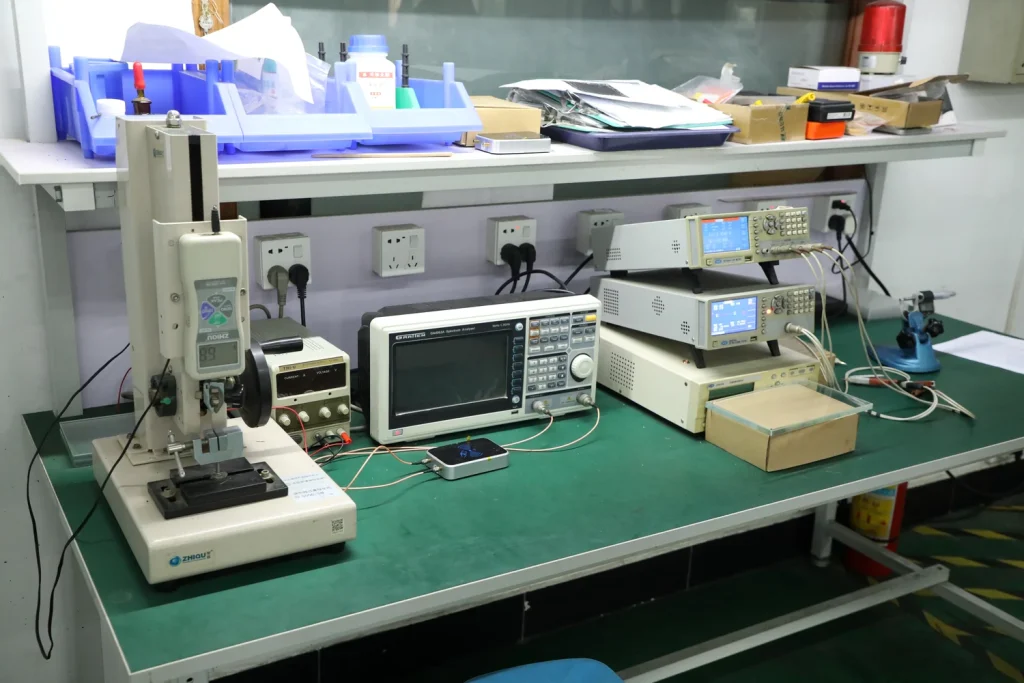
Use documented test conditions so sample approval and incoming inspection produce comparable results.
Supplier Qualification Questions for Procurement and Engineering
Ask prospective suppliers for evidence tied to the actual coil family:
- Can you manufacture from a drawing, physical sample, or electrical requirement and return a controlled production drawing?
- Which winding and connection steps are performed in-house?
- How are wire tension, turn count, bonding, and changeovers controlled?
- What measurement frequency, equivalent-circuit mode, fixture, and calibration system are used?
- Can you provide individual sample data and lot-level inspection records?
- How are wire lots, program revisions, equipment, and production dates traced?
- How will the coil be packaged to protect geometry and leads?
- What is the process for engineering changes, deviations, and corrective action?
- Can production samples be correlated with finished-tag test results?
- What information is needed to quote prototypes, pilot quantities, and volume production separately?
The most reliable answer is a documented process and sample data, not a tolerance claim in a sales message.
What to Send for an Accurate Custom-Coil Review
To reduce quotation cycles, send:
- Application and target market.
- Housing drawing or maximum coil envelope.
- Target inductance and tolerance with test conditions.
- Maximum DC resistance and any Q requirement.
- Wire and insulation requirements, if already defined.
- Lead, terminal, or chip-connection drawing.
- Assembly and encapsulation process.
- Expected prototype, pilot, and annual quantities.
- Required inspection report, traceability, packaging, and compliance documents.
- Existing sample and known performance issue, if this is a replacement or re-sourcing project.
If some values are not yet fixed, identify them as design inputs to be developed rather than leaving them implicit.
Custom RFID Sensing Coils From Sensync
Sensync custom RFID and NFC sensing coils can be developed from customer drawings, samples, or application requirements. Sensync’s broader custom electronic coil capability covers winding, production support, and inspection for different coil structures and sizes.
Sensync also develops automated winding equipment and supports projects from samples and pilot runs through volume production. This combination helps engineering and manufacturing teams discuss both the component design and how it can be produced consistently.

Sensync supports custom coil projects from sample development to production manufacturing.
For a practical review, contact the Sensync engineering team with your drawing, target electrical values, housing constraints, assembly process, and expected volume.
Frequently Asked Questions
What frequency is used for livestock RFID ear tags?
Many ISO-based LF animal-identification transponders operate around 134.2 kHz using FDX-B or HDX technology. Some markets and applications also use other technologies, including UHF. Confirm the required standard, approval scheme, readers, and tag architecture before defining the coil.
Can I specify an ear tag coil using inductance alone?
No. Inductance must be paired with measurement conditions, DC resistance, mechanical dimensions, lead or connection requirements, materials, packaging, and finished-tag validation criteria.
Does an ISO 11784/11785 reference make the coil compliant?
No. ISO 11784 and ISO 11785 apply to the animal-identification code and transponder communication concept. Conformance is evaluated at the transponder or finished-device level, not on an isolated wound coil.
Why can a coil pass incoming inspection but fail after molding?
Molding heat, pressure, coil movement, connection damage, material interaction, or a change in effective capacitance can shift the assembled response. Validate the coil after the actual production process and investigate the complete assembly.
What is the best way to compare two coil suppliers?
Use the same controlled drawing, materials, LCR test method, sample size, assembly process, and finished-tag test plan. Compare distributions and traceability records, not only the nominal values or unit price.


