
When designing electromagnetic coils for space-constrained electronics—such as smart rings, smart glasses, TWS earbuds, hearing aids, and ultra-thin wireless power transfer modules—every micrometer of vertical Z-height counts.
Many hardware engineering teams encounter an unexpected and frustrating roadblock during the transition from prototype to pre-production: the coil’s electrical parameters (inductance L, quality factor Q, and DC resistance Rdc) easily pass simulation, but the physical part interferes with the outer enclosure during final assembly. In nine out of ten cases, the culprit is the “return lead crossover bulge” inherent to conventional layer winding.

This is where Alpha winding (also known as center-out, bifilar reverse, or inside-out winding) becomes an indispensable manufacturing technology.
Below is an in-depth engineering comparison between Alpha winding and conventional layer winding, detailing why conventional layer winding fails thin enclosures, how Alpha winding kinematics eliminate crossover bulge, and the precise tooling specifications required for automated mass production.
1. Quick Summary: Layer Winding vs. Alpha Winding at a Glance
For component engineers, hardware architects, and sourcing managers, the table below contrasts the mechanical and electrical performance of both winding architectures:
| Parameter | Conventional Layer Winding | Alpha Winding (Center-Out) | Engineering Impact |
|---|---|---|---|
| Winding Progression | Starts at inner core, winds outward layer by layer | Starts at innermost core, winds both halves outward simultaneously | Eliminates return lead routed back across coil face |
| Lead Exit Geometry | One lead at inner core, one lead at outer perimeter | Both leads terminate at the outer circumference | Dramatically simplifies SMT soldering; no PCB trench needed |
| Z-Height Bulge | +1.0× to +1.8× wire diameter bulge | 0 μm added crossover height (flat plane within ±0.015 mm) | Eliminates mechanical interference inside compact enclosures |
| Slot Fill Factor | Moderate (80% – 88%) | Ultra-High (up to 92%) with self-bonding wire | Achieves higher inductance (L) and lower DCR in identical envelope |
| Dielectric Breakdown Risk | Elevated at cross-wire pinch points under pressure | Near zero (no intersecting wire paths under mechanical tension) | Higher manufacturing yield and superior long-term thermal reliability |
| Parasitic Capacitance (Cp) | Higher due to overlap between inner lead & outer turns | Lower & symmetric, raising self-resonant frequency (fSRF) | Superior high-frequency coupling in NFC and Qi2 wireless charging |
| Mass Distribution | Asymmetric (due to single-side crossing wire) | Concentric and dynamically balanced | Eliminates acoustic buzzing and rotational imbalance in LRAs / voice coils |
| Machine & Tooling Complexity | Standard multi-axis winding machine | Specialized dual-spindle / reverse-traverse system | Requires closed-loop dynamic tensioners and carbide tooling |
2. The Mechanical Problem: Why Layer Winding Fails Thin Enclosures
To understand why Alpha winding is essential, one must analyze the physical progression of conventional layer winding.
In standard layer-wound bobbin or air-core coils:
- The start lead is anchored at the inner diameter (ID) of the winding arbor.
- The winding spindle rotates, laying down consecutive turns along the traverse width until Layer 1 is complete.
- The wire steps up to Layer 2, winding back across Layer 1 toward the start side, repeating until the designated turn count is reached.
- The finish lead exits at the outermost layer.
The Return Lead Height Penalty
Because the start lead originates at the innermost diameter of the coil, it must physically cross over either the top face, bottom face, or outer flank of the finished winding to reach the PCB termination pads or flex circuit.
Even when smoothed down with polyimide (Kapton) tape or routed through a recessed plastic guide, this crossing wire creates an unavoidable local high spot:
Total Local Thickness = Nominal Coil Stack Height + dwire + tinsulation/tape
In an industrial transformer or automotive relay where total stack height is 20 mm, an extra 0.20 mm bulge is negligible. However, in modern ultra-thin consumer hardware:
- Smart Ring Cavity: Available vertical space for the antenna/charging coil is frequently restricted to 0.45 mm ± 0.03 mm. A 0.06 mm wire crossing with tape adds over 18% to the overall component thickness.
- Ultrasonic Welding & Housing Pinch: When the outer plastic or titanium housing is ultrasonically welded or pressed with structural adhesive, the localized high spot acts as a stress concentrator. This pinches the magnet wire, causing dielectric breakdown, micro-fractures in adjacent ferrite sheets, or cosmetic dimples on the exterior shell.
3. How Alpha Winding Works: Inside-Out Architecture & Kinematics
Alpha winding solves the return wire challenge by fundamentally rethinking winding kinematics. Instead of winding outward and dragging a lead back across, Alpha winding anchors the wire at its center transition point and winds both sections outward toward the outer perimeter.
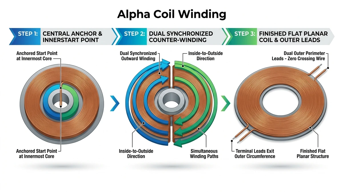
The 3 Core Steps of the Alpha Process:
- Step 1: Central Anchor & Transition Loop: The enameled magnet wire is clamped at its center point inside precision-ground tooling. The transition loop sits harmlessly in the empty inner core diameter of the coil.
- Step 2: Dual Synchronized Outward Counter-Winding: The winding machine simultaneously or sequentially winds both sections from the inside diameter outward to the outside diameter (OD). Because both halves progress outward, neither half ever has to cross over another active turn.
- Step 3: Finished Planar Coil & Outer Leads: Both the start lead and the finish lead terminate cleanly at the outer perimeter of the coil. They can be oriented at 0° (parallel), 90°, or 180° (diametrically opposed) depending on SMT solder pad layout.
Mechanical & Electrical Advantages:
- Absolute Planar Flatness: With zero crossing wires, the coil surface achieves true planarity within ±0.015 mm, providing seamless surface contact against planar ferrite sheets or PCB surfaces.
- Automated SMT Pick-and-Place: Surface mount nozzles can grip the flat face without vacuum leakage. SMT pads on the PCB only need contact areas around the outer edge, eliminating milled center slots or relief vias.
- Enhanced High-Frequency Q-Factor: By eliminating perpendicular cross-overs, inter-turn capacitive coupling is minimized, preserving a high quality factor (Q) and extending the self-resonant frequency (fSRF).
4. When Should You Specify Alpha Winding?
While Alpha winding requires specialized equipment, it is the engineering standard for three critical product categories:
1. Smart Wearables & Medical Micro-Sensors (Smart Rings, TWS, Hearing Aids)
Where total coil thickness must remain between 0.25 mm and 0.60 mm. Self-bonding Alpha coils can be thermally bonded bobbinless, maximizing magnetic coupling in ultra-thin cavities.

2. High-Efficiency Wireless Power Transfer (Qi2 MPP and NFC WLC)
In Qi2 Magnetic Power Profile (MPP) transmitter and receiver modules, magnetic coupling efficiency depends on uniform contact between the coil turns and the underlying ferrite shield. An uneven crossover bulge creates an unwanted air gap, degrading coupling coefficient (k) and increasing eddy current heat generation. Alpha coils ensure optimal planar coupling.
3. Precision Voice Coils & Miniature Linear Resonant Actuators (LRAs)
Miniature acoustic speakers and haptic vibration motors require symmetric moving mass. The concentric geometry of an Alpha coil prevents rotational wobble and buzzing during high-frequency vibration cycles.
5. Manufacturing Realities: Machine & Tooling Requirements
Alpha coils cannot be produced reliably on standard manual or general-purpose winding equipment. When sourcing an automated precision winding machine or auditing an OEM coil manufacturing partner, evaluate these three essential hardware capabilities:

1. Dynamic Closed-Loop Servo Tension Control
Alpha winding often employs ultra-fine magnet wire ranging from AWG 38 down to AWG 52 (0.10 mm down to 0.02 mm). Because the spindle must execute direction changes and dual-plane progression, any transient tension surge will stretch the copper, shifting DC resistance (Rdc) out of tolerance or snapping the wire. Sensync automated winders integrate electronic closed-loop tensioners maintaining tension stability within ±0.1 g.
2. Micro-Radiused Tungsten Carbide Tooling
Clamping the wire at the inner transition apex without scraping off the microscopic enamel insulation requires mirror-polished tungsten carbide tooling with precise micro-radii (R < 0.05 mm). Substandard tooling scratches the polyurethane or polyesterimide film, creating latent inter-turn shorts.
3. Synchronized In-Line Thermal Bonding Activation
Most Alpha coils for compact electronics are bobbinless air-core designs. Automated winding machines must integrate calibrated hot-air nozzles (180°C – 230°C) directly at the point of wire contact, or deliver precisely metered current pulses to melt the bondcoat (polyamide/polyvinyl butyral), locking the coil into a solid, rigid structure upon demolding.
6. Engineering Drawing & RFQ Specification Checklist
When requesting a quotation or engineering prototype for custom electronic coils, generic notes such as “wind flat” lead to manufacturing ambiguity. Ensure your 2D manufacturing drawings include:
- Maximum Allowable Z-Height (with Tolerance): e.g., 0.35 mm ± 0.02 mm total finished stack height including bondcoat layer.
- Lead Exit Orientation & Stripping Specs: Specify radial exit angle (0° parallel, 90°, or 180° opposed), stripped enamel length, and tinning lead alloy (e.g., lead-free SAC305).
- Inner Core Transition Radius: Specify allowable internal bend radius to prevent copper work-hardening.
- Target Inductance (L) & DCR at Test Frequency: e.g., L = 6.8 μH ± 5% @ 100 kHz, 1 V; Rdc ≤ 320 mΩ @ 25°C.
- Ferrite & Adhesive Integration: If an integrated shielding sheet is required, specify ferrite permeability (μr) and adhesive liner thickness (e.g., 0.03 mm 3M 467MP).
7. Frequently Asked Questions (FAQ)
Q1: Is Alpha winding more expensive than standard layer winding?
A: The initial tooling cost and per-unit cycle time are marginally higher (typically 10% to 18%) due to dual-spindle synchronization and precise wire handling. However, in space-critical assemblies, Alpha winding drastically reduces total system cost by eliminating secondary manual taping, eliminating PCB relief routing, and preventing assembly line interference scrap.
Q2: Can Litz wire be wound using the Alpha method?
A: Yes. Multi-strand Litz wire (such as 15 × 0.04 mm or 25 × 0.05 mm) can be Alpha wound for high-frequency wireless power transfer and induction heating. Sensync equipment utilizes custom guide rollers designed specifically for profiled and non-circular wire geometries to prevent strand crossing.
Q3: How thin can an Alpha-wound coil realistically be manufactured?
A: Utilizing self-bonding ultra-fine copper wire (AWG 46–50), Sensync routinely mass-produces bobbinless Alpha coils with single-plane thickness as low as 0.25 mm to 0.35 mm, maintaining structural rigidity and thermal stability up to 155°C (Class F) or 180°C (Class H).
Q4: Does Alpha winding require a plastic bobbin?
A: No. The vast majority of Alpha coils are completely bobbinless (self-supporting air core coils). The adhesive coating on the enameled wire is activated during or immediately after the winding cycle via heated air or electrical pulse bonding, eliminating bobbin wall thickness entirely.
8. Summary: Scaling Repeatable Coil Production
The difference between a functional laboratory prototype and high-yield volume production often hinges on how a single strand of copper wire exits the coil structure. By moving from conventional layer winding to Alpha winding, hardware teams gain critical vertical headroom, eliminate high-pressure dielectric failure points, and enable streamlined surface-mount automation.
Partner with Sensync for Coil Feasibility & Equipment
Whether you require automated precision winding machinery to scale your in-house manufacturing or an experienced tier partner for custom precision electronic coil production, Dongguan Sensync Technology Ltd. delivers over 25 years of engineering expertise and Apple supply chain-qualified manufacturing standards.
👉 Contact Our Engineering Team today to review your coil drawings, request feasibility evaluations, or receive custom prototype samples.


