

Brushless motors dominate many new product discussions, but brushed DC motors remain a practical choice wherever simple control, compact packaging, proven architecture, and controlled unit cost matter. Automotive auxiliary systems, pumps, power tools, household appliances, and industrial micro motors still create substantial demand for reliable brushed DC motor rotor production.
For manufacturers serving these applications, the real question is not whether brushed motors are still relevant. It is whether the winding process can deliver the required output and repeatability without depending on continuous manual adjustment. A brushed motor rotor winding machine addresses that production problem by controlling the winding sequence, position change, wire arrangement, and cutting through a repeatable machine program.
This guide explains when 4-axis rotor winding automation makes sense, how it differs from manual winding, and what engineers should confirm before choosing equipment.
Key Takeaways
- Brushed and brushless motors serve different cost, control, and performance requirements; growth in brushless technology does not eliminate the need for efficient brushed-motor production.
- A 4-axis machine processes four rotors in parallel, but actual output still depends on rotor geometry, wire size, turn count, loading method, and cycle settings.
- Automation improves repeatability by moving key variables from operator technique into saved machine recipes and servo-controlled motion.
- The Sensync machine described here is designed for brushed outer rotors up to Φ45 mm and enameled copper wire from 0.2 to 1.2 mm.
- Buyers searching for an automatic armature winding machine should first confirm the rotor architecture, because armature and outer-rotor tooling are not automatically interchangeable.
Brushed vs. Brushless Is an Application Decision, Not a Deadline
It is easy to describe brushless technology as the universal replacement for brushed motors. In practice, motor selection depends on the complete system: controller complexity, target lifetime, duty cycle, acoustic limits, available space, production volume, and cost.
Brushless motors are often preferred when long service life, electronic commutation, high efficiency, or precise speed control justify the additional electronics. Brushed DC motors remain attractive when the application values straightforward drive control, established supply chains, compact construction, and competitive total cost.
That is why brushed motors continue to appear in window-lift and seat actuators, pumps, mixers, vacuum cleaners, electric tools, fans, toys, and many small-motion systems. Even when a new premium platform moves to brushless technology, existing brushed product families may remain in production for years. Manufacturers still need a stable way to produce their rotors.
Why Rotor Winding Has an Outsized Effect on Motor Consistency
Rotor winding looks repetitive, but several process variables interact on every part:
- Turn count: The programmed number of turns helps determine the coil’s electrical and magnetic behavior.
- Wire placement: Neat, controlled arrangement reduces the risk of crossed wire, local buildup, and interference with later assembly.
- Position accuracy: The winding nozzle and rotor must align consistently as the machine moves between winding positions.
- Wire handling: Starting, direction change, transfer, and cutting must be completed without damaging the enamel insulation.
- Recipe control: Speed, turns, movement, and related settings should be repeatable when a product returns to production.
In a manual process, these variables depend heavily on operator technique and attention. Semi-automatic equipment may control spindle rotation while leaving more positioning or handling steps to the operator. A multi-axis automated system brings more of the sequence into one controlled recipe.

Manual Winding vs. a 4-Axis Brushed Motor Rotor Winding Machine
The most useful comparison is not “human versus machine” in the abstract. It is which variables are controlled, how many workpieces are processed at once, and where operator judgment remains necessary.
| Evaluation point | Manual or basic semi-automatic winding | 4-axis automated winding |
| Workpieces per winding cycle | Commonly one workpiece at a time | Four rotors can be wound simultaneously |
| Turn count and motion | More dependent on operator setup and monitoring | Controlled by the winding program and servo motion |
| Position shifting | Manual or partially automated | Automatic position shifting between programmed locations |
| Wire arrangement | Dependent on operator technique or basic traverse control | Programmed automatic wire arrangement |
| Wire cutting | Often a separate manual step | Automatic wire cutting is included in the machine sequence |
| Product changeover | Relies on manual settings, notes, and tooling changes | Saved recipes support parameter recall; tooling still must match the rotor |
| Operator role | Direct winding and frequent intervention | Loading, unloading, setup verification, monitoring, and quality checks |
| Best fit | Sampling, repair, very low volume, or highly variable work | Repeat production where four-up processing and controlled recipes are valuable |
Four axes do not guarantee exactly four times the finished output. Loading time, wire diameter, turn count, transfer motion, cutting, inspection, and downstream handling all affect the final cycle. A realistic equipment evaluation should use the customer’s actual rotor, wire, and target process rather than a generic speed claim.
What Changes When Winding Parameters Move Into the HMI
Recipe-based control is one of the most important differences between a basic winding station and a production-oriented automated machine. Through the touchscreen HMI, the operator can set relevant process values, save product programs, and recall them when switching between approved specifications.
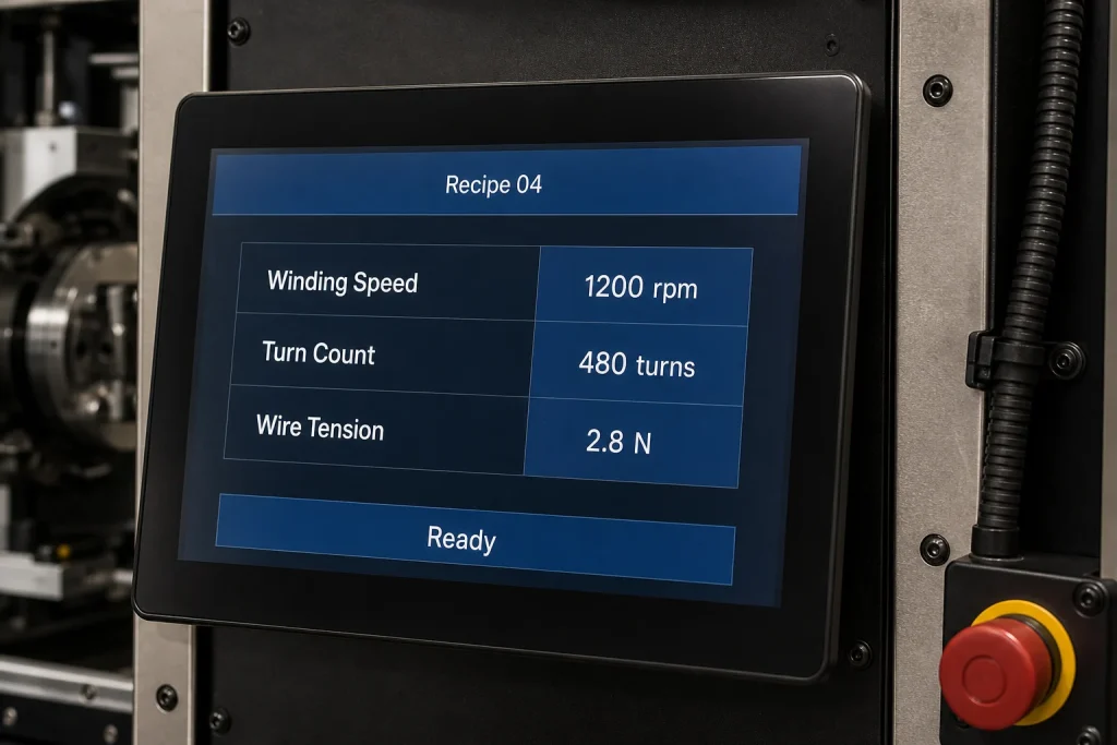
Illustrative HMI concept for explaining recipe control. The actual Sensync interface and available parameters depend on the confirmed machine configuration.
Recipe recall reduces repeated data entry, but it does not remove the need for process validation. After any tooling change or recipe selection, the team should verify the rotor fixture, wire path, nozzle clearance, winding direction, turn count, and sample quality before releasing a full batch.
How a 4-Axis Winding Workflow Operates
The exact sequence depends on the rotor and tooling, but a typical automated cycle follows this logic:
- The operator or feeding system loads four compatible rotors into the fixtures.
- The machine confirms the starting positions defined by the selected recipe.
- Four winding axes operate in parallel under servo control.
- The system changes direction and shifts position according to the programmed winding path.
- Automatic wire arrangement helps place wire consistently as the cycle progresses.
- The machine completes the programmed turns and cuts the wire.
- The finished rotors are unloaded for the next operation or quality check.
For higher-volume lines, an optional loading and unloading robot can reduce manual handling between cycles. Integration should be planned around part orientation, buffer capacity, safety guarding, upstream feeding, and downstream processes rather than treated as a bolt-on accessory at the end of the project.
Technical Parameters to Confirm Before Buying
The 4-Axis Brushed Motor Rotor Winding Machine from Sensync is Model ZGMD-Z4-HA1. Its published base specifications are:

Published specifications are a starting point. Final tooling and machine configuration must be confirmed against the rotor structure, wire, process, and automation requirements.
| Specification | Published value |
| Number of axes | 4 axis |
| Applicable product | Brushed outer rotor |
| Wire diameter range | 0.2-1.2 mm |
| Supported wire | Enameled copper wire |
| Product size range | ≤ Φ45 mm |
| Control system | Mitsubishi servo system + touchscreen HMI |
| Main functions | Automatic winding, direction change, position shifting, wire arrangement, and wire cutting |
| Power input | AC 380 V ±10%, 50 Hz |
| Power consumption | 6.3 kW |
| Machine dimensions | 1200 × 1250 × 1950 mm |
| Machine weight | Approx. 600 kg |
Beyond the specification table, ask the prospective 4-axis winding machine manufacturer to review:
- rotor drawings, samples, and critical dimensions;
- slot or winding geometry and required wire path;
- wire material, enamel grade, and full diameter range;
- turns, winding direction, and changeover frequency;
- target cycle time and daily output;
- start, transfer, termination, and cutting requirements;
- inspection standards and sample-approval criteria;
- manual loading versus automatic feeding;
- factory power, floor space, guarding, and line interface requirements.
Application Fit for Brushed DC Motor Rotor Production
Automotive Auxiliary Motors
Window-lift, seat-adjustment, mirror, lock, wiper, and related auxiliary systems may use brushed DC motors where compact drive architecture and cost control are important. For suppliers in automotive programs, repeatable winding must be considered alongside traceability, incoming wire control, tooling maintenance, and downstream electrical testing.

Illustrative application image. Actual automotive motor architecture and rotor geometry vary by program.
Home Appliance Motors
Mixers, vacuum cleaners, fans, and other small appliances often combine high production volume with tight cost targets. Rotor winding automation can help stabilize the winding sequence while allowing the operator to supervise multiple workpieces instead of manually forming every coil.

Illustrative application image showing typical brushed-motor components; not a specific Sensync customer product.
Pumps, Power Tools, and Industrial Micro Motors
Water-pump motors, drills, grinders, actuators, and other compact brushed systems can also benefit from controlled turn count, repeatable position shifting, and stable wire handling. The business case becomes stronger when a rotor family repeats often enough to justify dedicated tooling and recipe validation.

Illustrative armature close-up. Buyers should confirm whether their product requires an armature winding machine or an outer rotor winding machine.
Outer Rotor Winding Machine or Automatic Armature Winding Machine?
These search terms are sometimes used loosely, but they should not be treated as interchangeable equipment categories.
An outer rotor winding machine is designed around the geometry, access, and tooling requirements of an external rotating structure. An automatic armature winding machine typically handles a laminated armature core mounted on a shaft, often with a commutator and different wire-guiding or hooking requirements.
Sensync’s ZGMD-Z4-HA1 is specified for brushed outer rotors. If your sample is a conventional shaft-mounted armature, send the drawing and physical sample for technical review before assuming this model is suitable. This one clarification can prevent a costly mismatch between a keyword search and the actual winding process.
When a 6-Axis Brushless Stator Machine Is the Better Match
If the part is a brushless stator rather than a brushed rotor, evaluate a machine designed for that geometry. Sensync’s 6-Axis Brushless Motor Stator Winding Machine winds six stators simultaneously and is specified for brushless stator applications.
The choice should follow the component in front of you:
- brushed outer rotor: evaluate the 4-axis rotor machine;
- conventional brushed armature: request an armature-specific process review;
- brushless stator: evaluate the 6-axis stator machine or another stator-specific configuration.
A Practical ROI Framework for Rotor Winding Automation
Avoid calculating return on investment from labor savings alone. A better evaluation includes:
- acceptable parts per shift using the actual winding recipe;
- number of operators required for loading, inspection, and material replenishment;
- scrap and rework associated with winding defects;
- changeover frequency and tooling cost;
- maintenance time and spare-part strategy;
- downstream savings from more consistent winding;
- whether robot loading is needed now or can be planned as a later phase.
Ask the machine supplier to run representative samples, document the agreed cycle, and define acceptance criteria. This turns a general automation claim into a measurable project.
Frequently Asked Questions
Can the machine wind four different rotor models at the same time?
The four-axis design is intended for synchronous production of compatible rotors under one recipe and tooling setup. Mixing unrelated rotor models in one cycle should not be assumed. Confirm any special multi-product requirement during technical evaluation.
Does recipe recall make changeover fully automatic?
No. Recipe recall can restore approved parameters, but the correct fixtures, winding tools, wire path, and mechanical clearances still need to be installed and verified. The total changeover time depends on how different the two products are.
Is 0.2-1.2 mm wire supported for every rotor size?
The published machine range is 0.2-1.2 mm enameled copper wire, but the feasible combination of wire diameter, turns, rotor geometry, and speed must be confirmed for each project.
Can the machine be integrated into a fully automatic line?
Yes, the product can be configured with a loading and unloading robot. The integration plan should also define feeding, orientation, buffering, safety, communications, and the receiving process after winding.
What should I send for a technical assessment?
Provide the rotor drawing and sample, wire specification, winding data, target output, present process, inspection requirements, and any upstream or downstream automation constraints. A short video of the current process can also help the engineering review.
Discuss Your Rotor Winding Project with Sensync
Sensync’s 4-axis system combines four-up synchronous winding, servo control, automatic position shifting, wire arrangement, direction change, cutting, recipe storage, and optional robotic handling for brushed outer-rotor production.

Rotor structure determines fixture and winding-program design.
If you are evaluating rotor winding automation, contact our engineering team with your rotor drawing, wire range, turns, and production target. Sensync can review whether the 4-axis configuration fits the part and propose the next technical steps.


